Multi-Split PV Modules: Analysis of Shade Resistance Performance
Starting from 2025, the concept of "multi-split cells" has regained widespread popularity in the photovoltaic industry. At this year’s SNEC Exhibition, major module manufacturers unveiled new designs including three-split and four-split cell configurations. It appears that module producers are no longer satisfied with half-cut cells and have begun in-depth research on how many times a single solar cell wafer can be divided. This article elaborates on what multi-split modules are, why they have gained industry attention, and their strengths as well as limitations in terms of shade resistance.
Definition of Multi-Split Cells
The term "multi-split cell" generally refers to cutting a complete solar cell wafer into multiple smaller cell units, which are then encapsulated in series or parallel connections. Common configurations are as follows:
- Half-cut cell: A full wafer split into 2 equal pieces (mainstream technology)
- Three-split cell: A full wafer divided into 3 segments
- General multi-split cell: Wafers cut into more smaller units, such as four-split, five-split and six-split cells
Shingled modules can also be regarded as a special type of multi-split cell application.
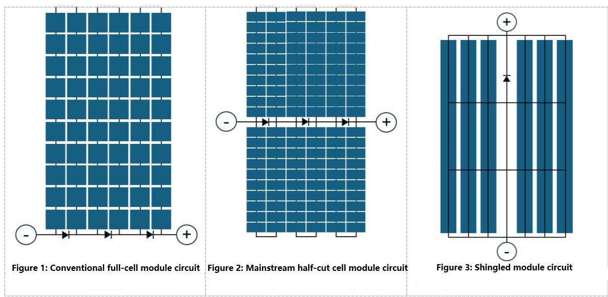
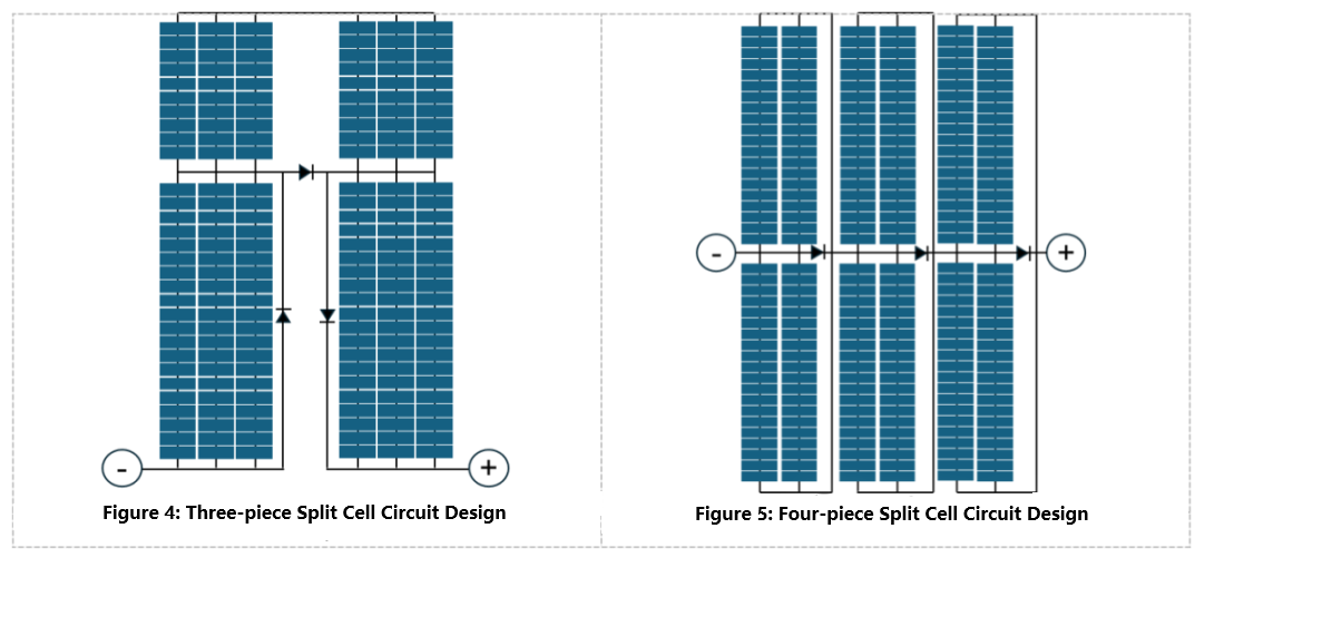
Note: The figures show typical circuit schematics only, not the actual product designs of individual manufacturers.
Core Purposes of Multi-Split Design
The core objective of multi-split cell design is to reduce operating current of individual cell units and optimize the internal circuit connection scheme of modules, so as to cut power loss and improve the power generation performance of modules under complex operating conditions.
Its main advantages are as follows:
-
Reduced operating current
After solar cells are cut into smaller segments, the operating current of each split cell unit decreases correspondingly.
-
Lower resistive power loss
The resistive power loss inside a PV module is proportional to the square of current, following the formula Ploss=I2R
Therefore, when the operating current drops, resistive power loss on ribbons and all internal conductive paths of the module will decline accordingly.
-
Improved module output power
Thanks to the reduction of internal resistive loss, the output power of modules under standard test conditions (STC) can generally be increased to a certain extent.
-
Mitigated hot spot risk
A lower operating current helps reduce heat generation risk under partial shading, thus alleviating the hot spot issue.
-
Higher shading tolerance
With rational circuit design, the adverse impact caused by partial shading can be confined to a small area, allowing unshaded segments to maintain power generation continuously.
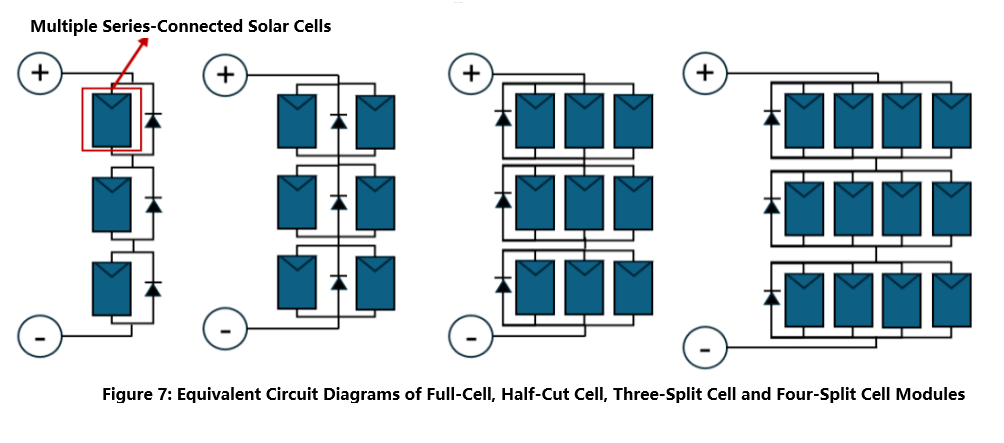
Therefore, through finely divided circuit partitions and parallel branch design, multi-cut modules can maintain favorable output performance under partial shading conditions. Its fundamental design concepts are as follows:
- Slice solar cells into smaller power generation units;
- Achieve the required module voltage via rational series connection;
- Reduce the current of each single branch by adopting parallel paths;
- Limit power loss in shaded areas with bypass diodes;
- Maximize the normal power generation of unshaded regions.
Matters Needing Attention
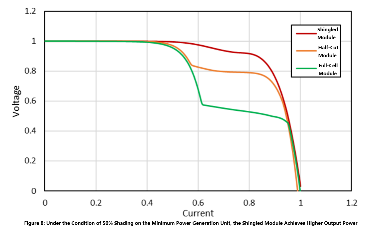
Although this paper mainly discusses the improvement of shading resistance brought by multi-cut circuit design, multi-cut modules do not necessarily have advantages under all shading scenarios.
The point emphasized above is that multi-cut modules usually deliver higher output power when the proportion of shaded cell area is identical. Nevertheless, under shadows of the same size and shape, the smaller area of sliced cell units may lead to a higher shading ratio, which in turn reduces the output power.
For instance, shading occurs along the short edge of the module, especially during early morning or late afternoon at power stations with low solar elevation angles. The shadow may cover the bottom row of cells on the module. For half-cut modules, the bottom row of cells may only be 70% shaded. In contrast, four-cut cells feature a smaller vertical height for each slice. The same shadow may fully cover the bottom row of sliced cells, resulting in a sharp drop in power output of the corresponding circuit section and even zero power generation from partial cell strings.
Furthermore, three-cut modules may exhibit vertical asymmetry due to their layout and circuit design. When shadows of equal area and shape fall on both sides of the module, the actual power loss incurred may differ. Under certain specific shading conditions, three-cut modules may even suffer greater power loss than half-cut modules.
Therefore, when evaluating power loss caused by shading, it is insufficient to merely consider the shaded area. Comprehensive analysis must be carried out combining the actual internal series-parallel circuit layout of the module, the protection zones of bypass diodes, as well as the shape and position of shadows.
From High Power to High Generation Resilience
As the rated power of photovoltaic modules keeps rising, industry competition is no longer merely focused on pursuing peak power under standard test conditions (STC). For actual power plants, the long-term power generation capacity and stability of modules under complex operating environments have become far more critical.
Multi-cut modules such as four-cut modules adopt finer segmented cell units, lower operating current and more flexible series-parallel circuit design, which can effectively mitigate the impact of partial shadows on the overall module output. Their core value lies in localizing shadow losses and enabling unshaded areas to continuously generate electricity, thus improving the power generation stability of modules in real-world application scenarios.
In application scenarios prone to partial shading, including commercial and industrial rooftops, residential rooftops and building-integrated photovoltaics (BIPV), four-cut modules are expected to become a vital technical solution to boost system power generation revenue and operational reliability.


