Tabber Stringer Key Knowledge
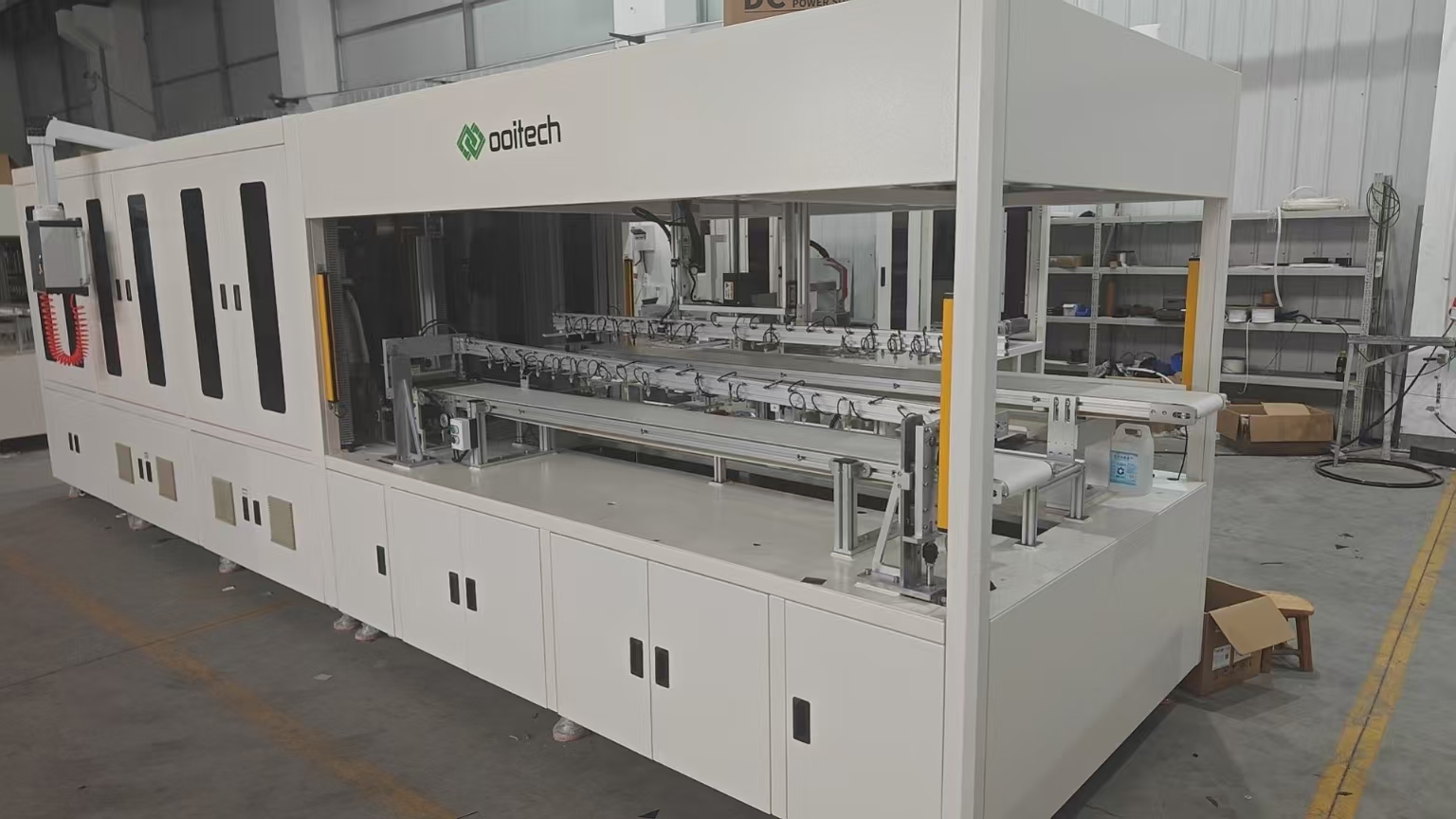
Tabber Stringer: Core equipment in PV module production lines. It uses tinned copper ribbons to connect solar cells in series into a cell string, which is the cell interconnection process. It directly affects module power, microcrack rate and long-term reliability, compatible with PERC, TOPCon, HJT, BC and other cell technologies.
1. Machine Structure
-
Cell loading unit: Magazine, vacuum manipulator, vacuum pick-up, automatic sheet separation to avoid double sheets and broken cells
-
Ribbon feeding & processing unit: Unwinding, tension control, flux spraying, straightening, cutting and forming. Function of flux: remove oxide layer and improve tin wettability
-
CCD vision positioning system: Image correction, positioning accuracy ±0.1 mm; identify broken cells, chipped edges and busbar offset, guide ribbon alignment with busbars
-
Preheating platform: Bottom preheating to reduce temperature difference and lower microcrack risk caused by thermal shock
-
Welding unit (core): IR / hot air / laser heating with mesh/pin pressing to achieve metallurgical bonding by melting tin coating
-
Conveying, flipping and unloading unit: Belt transmission, cell string turnover, buffer tray
-
In-line inspection: Visual inspection; some models integrate EL inspection to detect cold solder, offset welding, broken fingers and microcracks
-
Electric control system: Servo, temperature control, pneumatic, vacuum, HMI and alarm logic
2. Comparison of mainstream welding technologies
-
Infrared welding (mass production mainstream): Surface heating by IR lamps at 250–350℃. Uniform heat, stable yield and low maintenance cost. Suitable for multi-busbar and thin silicon wafers. Disadvantage: relatively high overall heat input
-
Hot air welding: Non-contact heating with high-temperature hot air; rarely used on new lines now
-
Laser welding (new generation, trend for BC & thin wafers): 1064 nm fiber laser for localized spot heating. Small heat-affected zone, low thermal stress and fewer microcracks. Suitable for ultra-thin cells / busbarless cells. Drawbacks: high cost of optical system, sensitive parameters and extremely high alignment requirement for fingers
Welding three key factors: temperature, pressure, welding time
-
Temperature: 20~30℃ above solder melting point. Excessively high: cell burnout, microcracks and silver busbar damage. Too low: cold solder joint
-
Pressure: 5–15 N. Insufficient pressure → poor bonding; excessive pressure → thin wafer cracking
-
Time: 200–800 ms. Too short: insufficient wetting; too long: tin flow and short circuit, cell thermal damage
3. Basic Process Flow
Cell loading → CCD preliminary visual inspection → vacuum positioning & preheating → ribbon feeding, flux coating, cutting & forming → ribbon stacked on cell busbar → heating + pressing welding → next cell stacking (back pad of previous cell connects front busbar of next cell) → continuous stringing → post-weld visual recheck / EL inspection → flipping, unloading to tray, transfer to lay-up / lamination process
4. Glossary
-
BB (Busbar): 2BB/3BB/5BB/9BB/12BB / MBB (Multi-Busbar). More busbars reduce current transmission loss and adopt thinner ribbons
-
Tinned copper ribbon: Copper substrate coated with tin-lead or lead-free tin; lead-free ribbon is mainstream in production currently
-
Cold solder joint: Tin fails to fully wet the busbar, low pulling force, rising resistance and power degradation after high-temperature aging
-
Over-welding: Excessive temperature causes tin overflow, silver busbar corrosion and breakage
-
String gap: Gap between adjacent cells, normally 1.8–3 mm. Shingled welding: zero gap and overlapping
-
Microcrack: Internal micro-fracture of silicon wafer induced by thermal stress or mechanical pressure, often invisible visually and detectable by EL
-
Pull test: Reliability index of solder joint; standard requirement: solder joint pulling force ≥0.5 N
5. Common Defects, Root Causes
-
Cold solder joint: Low temperature, insufficient/failed flux, inadequate pressure, oxidized ribbon or insufficient preheating
-
Offset welding (ribbon off busbar): Drifted CCD calibration, unstable ribbon tension, dirty guide groove or manipulator positioning deviation
-
Microcrack: Fast temperature ramp, excessive pin pressure, ultra-thin wafer, vacuum suction impact or large temperature difference
-
Twisted ribbon / exposed copper: Worn feeding guide groove, inconsistent left-right tension or deformed raw ribbon
-
Tin bridging short circuit: Over-temperature, long welding time, thick tin coating on ribbon or offset pressing mesh
-
Broken cell: Overstrong vacuum suction, impact from pressing head, inherent microcrack or transmission jam
6. Equipment Selection & Capacity Parameters
Compatible sizes: 166/182/210/230 mm large-format cells, also half-cut, 1/3-cut, 1/5-cut cells
Capacity: High-speed models reach 3600–4500 cells per hour for full cells; affected by busbar quantity, on-line EL, double-string function
Special models: BC-dedicated stringer, laser stringer, shingled stringer, laser dicing & stringing integrated machine
7. Related Processes
Matched with laser non-destructive dicing machine: Dicing first then stringing to reduce fragmentation.
BC (Back Contact) cells: No front-side busbars, demanding higher stringer positioning accuracy, ribbon forming and thermal welding control; it is the main upgrade direction for stringers.